Tracking ADS-B Signals with DIY Antenna & Raspberry Pi
Equiptment Setup
RG6U coaxial cable that included a datasheet was purchased through a local electronics supplier here in Calgary, Alberta.
The prospect of finding coaxial cable that came with a data sheet was surprisingly difficult; the data sheet was a requirement
in building a coaxial colinear antenna (COCO antenna).Due to the dielectric properties of coaxial cable, the velocity of propagation
(often times called the velocity factor, or VF) is different in coaxial cable than it is in air;
the velocity of propagation for ADSB signals in air is the speed of light,
whereas in the coaxial cable purchase, the velocity of propagation is 78% the speed of light.
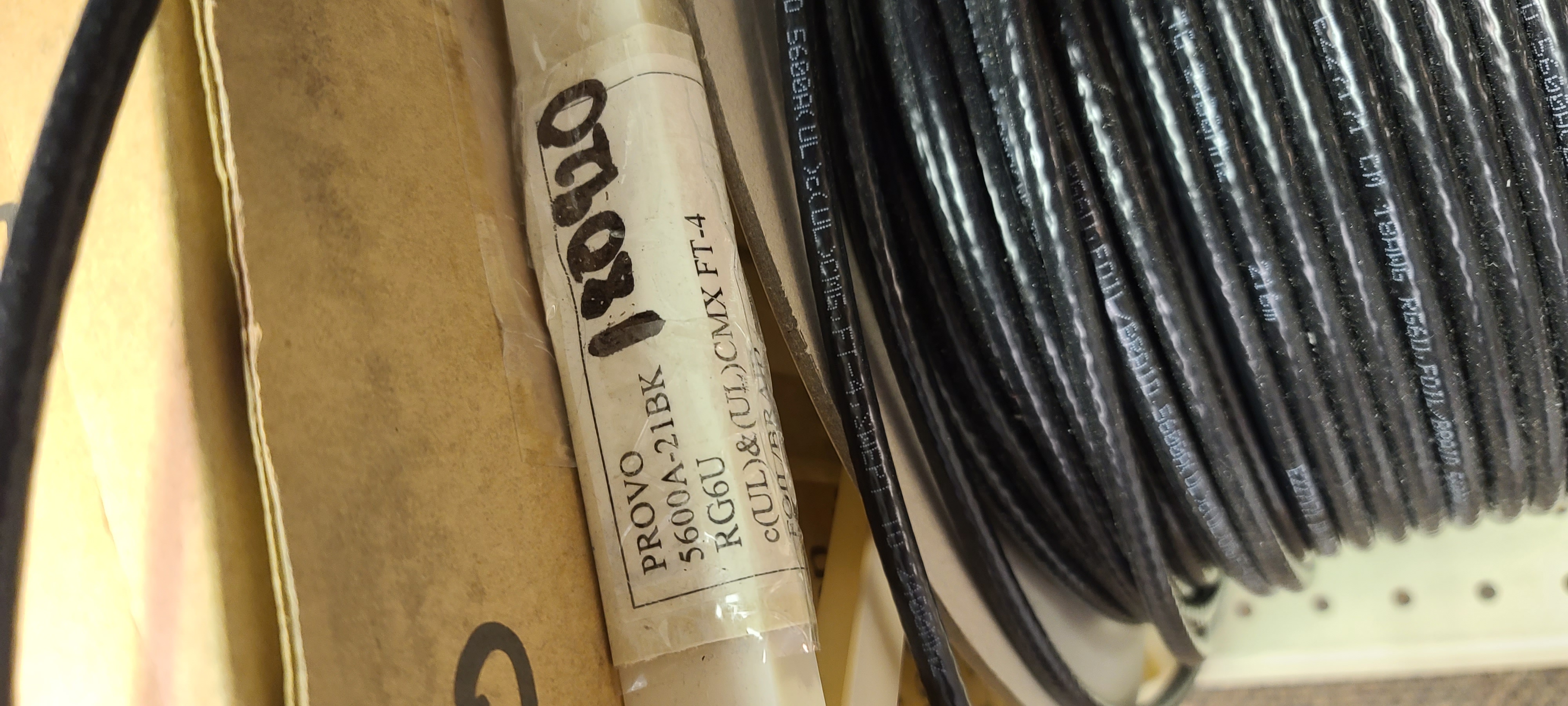
Figure 1: RG6U Coaxial Cable with VF=0.78
A coaxial colinear antenna used for receiving ADSB signals, is build by cutting precise strips of coaxial cable which are equal to 1/2 the wavelength
(typically these antennas are made with 4, 8, 12, or 16 separate 1/2 wavelength long coax). Due to the VF being different in the cable, '
the wavelength of the ADSB signal must be multiplied by this velocity factor, or velocity of propagation factor. The wavelength of an ADSB signal in air
is equal to approximately 275 mm; multiplying this by the velocity factor of 0.78 and dividing the result by 2,
we get a half wavelength of approximately 107.4 mm.
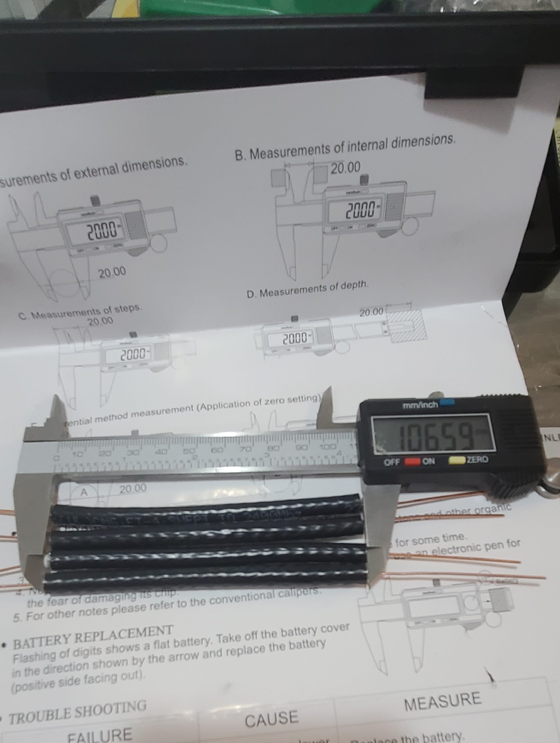
Figure 2: Four 1/2 Wavelength Strips of Coaxial Cable
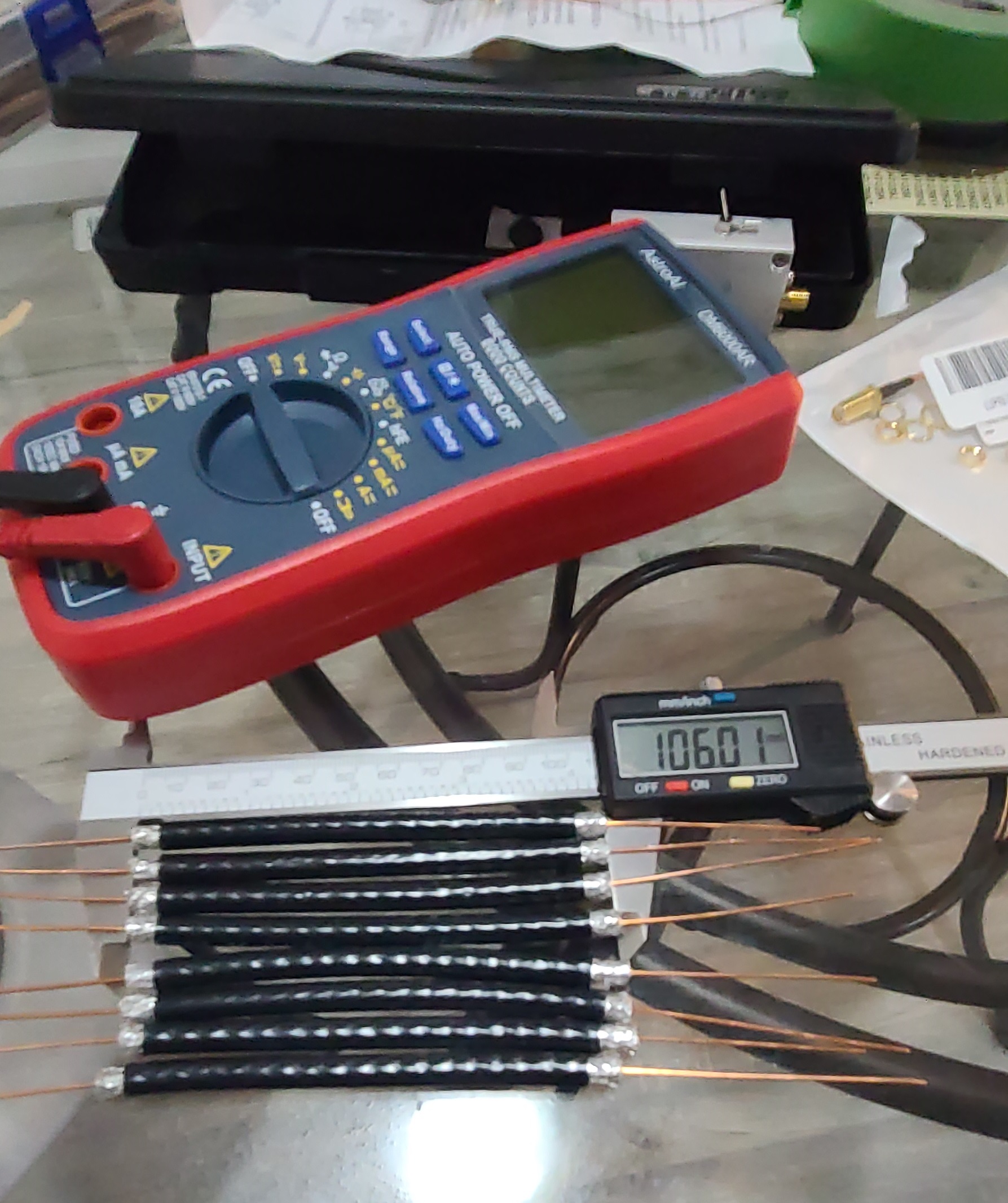
Figure 3: Eight 1/2 Wavelength Strips of Coaxial Cable
To make precise measurements, a caliper was purchased and sections of wavelengths were cut (a millimetre or so smaller to account for increased length
caused by attaching the coaxial strips). The first of two antennas was constructed using 4 sections of
coaxial cable and the second was constructed using 8 sections of coaxial cable (see figures 2 and 3).
The coaxial lengths were put together by reversing the inner and outer conductors with strips of electrical tape in between them to ensure that they would
not cause a short in the antenna (see figure 4).
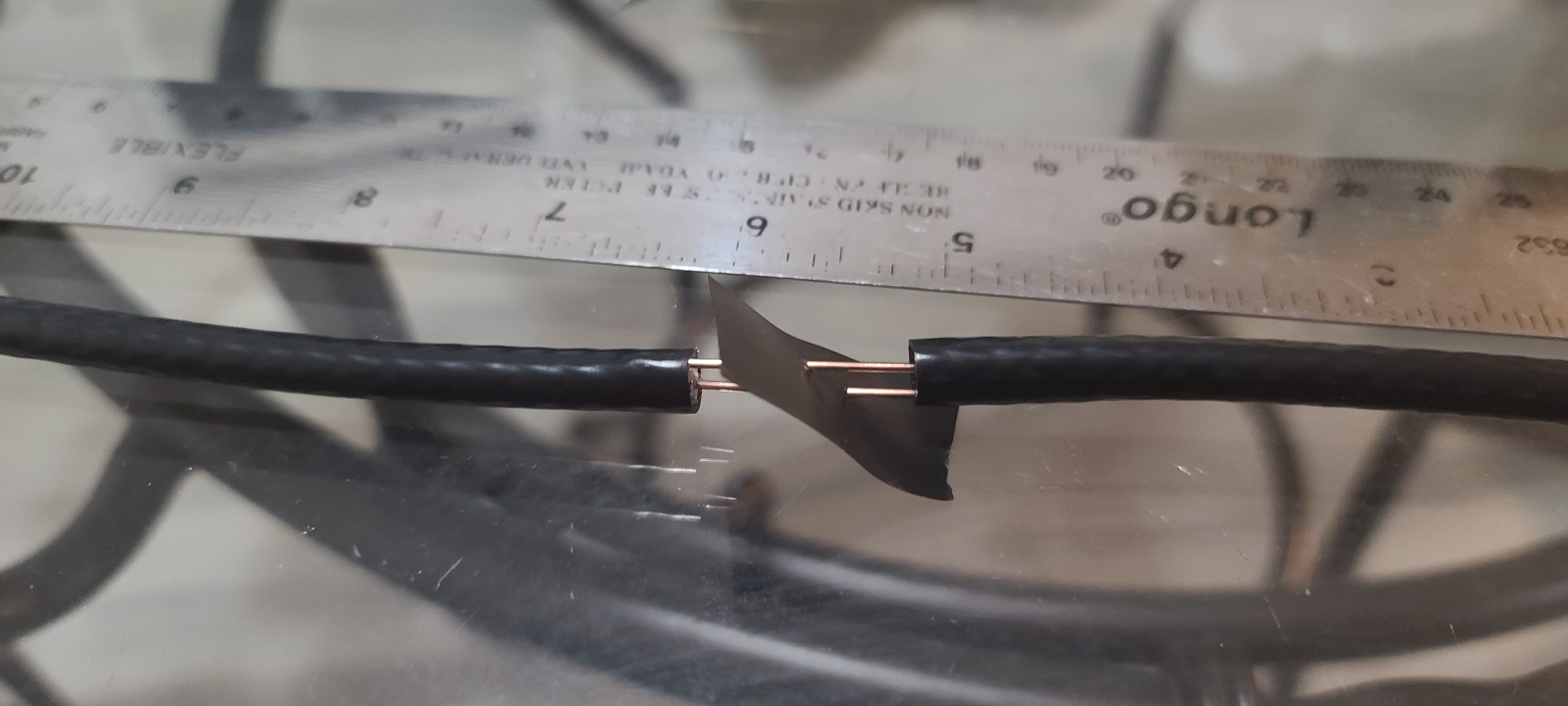
Figure 4: Connected 1/2 Wavelength Coaxial Strips
After each connection was made, electrical tape was wound tight around the outside of the antenna to ensure there was solid insulation around the antenna and to provide
a measure of structural strength. A resistor was placed between the inner and outer conductors at the top of the antenna so that a DMM could be used to perform
continuity tests and confirm that the correct value of resistance was being measured (see figure 5). A twist-on female coaxial connector was added to provide
connection to the rest of the circuit (see figure 6).
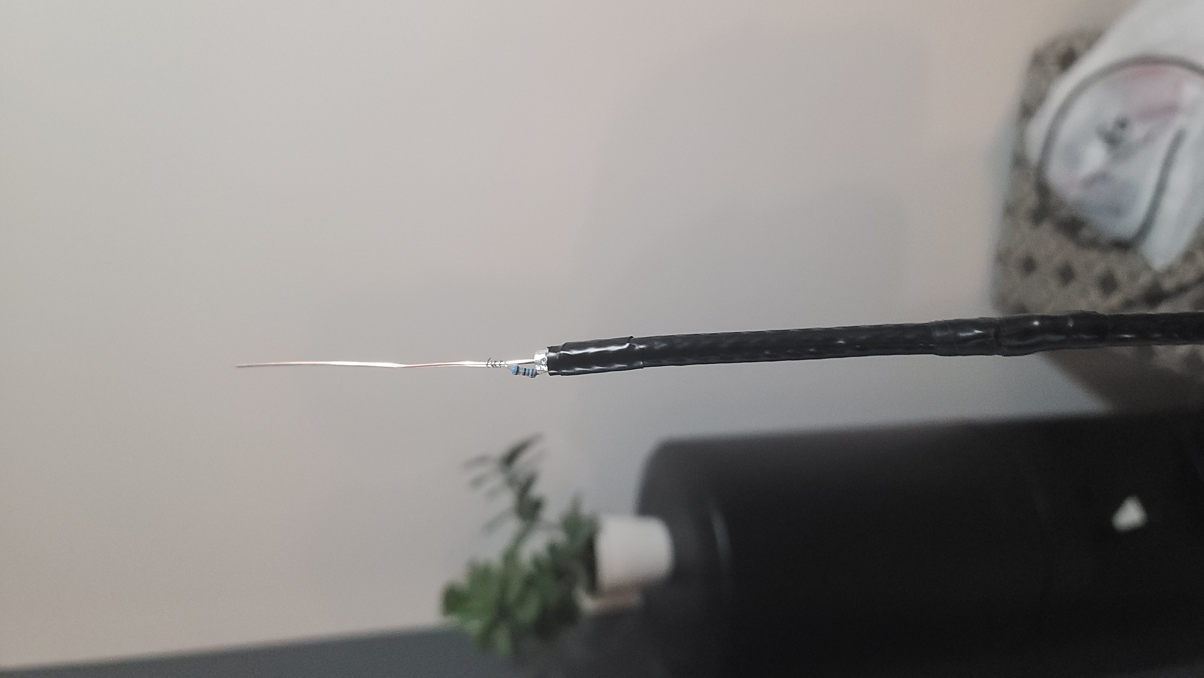
Figure 5: 50 Ohm Resistor for Testing Purposes
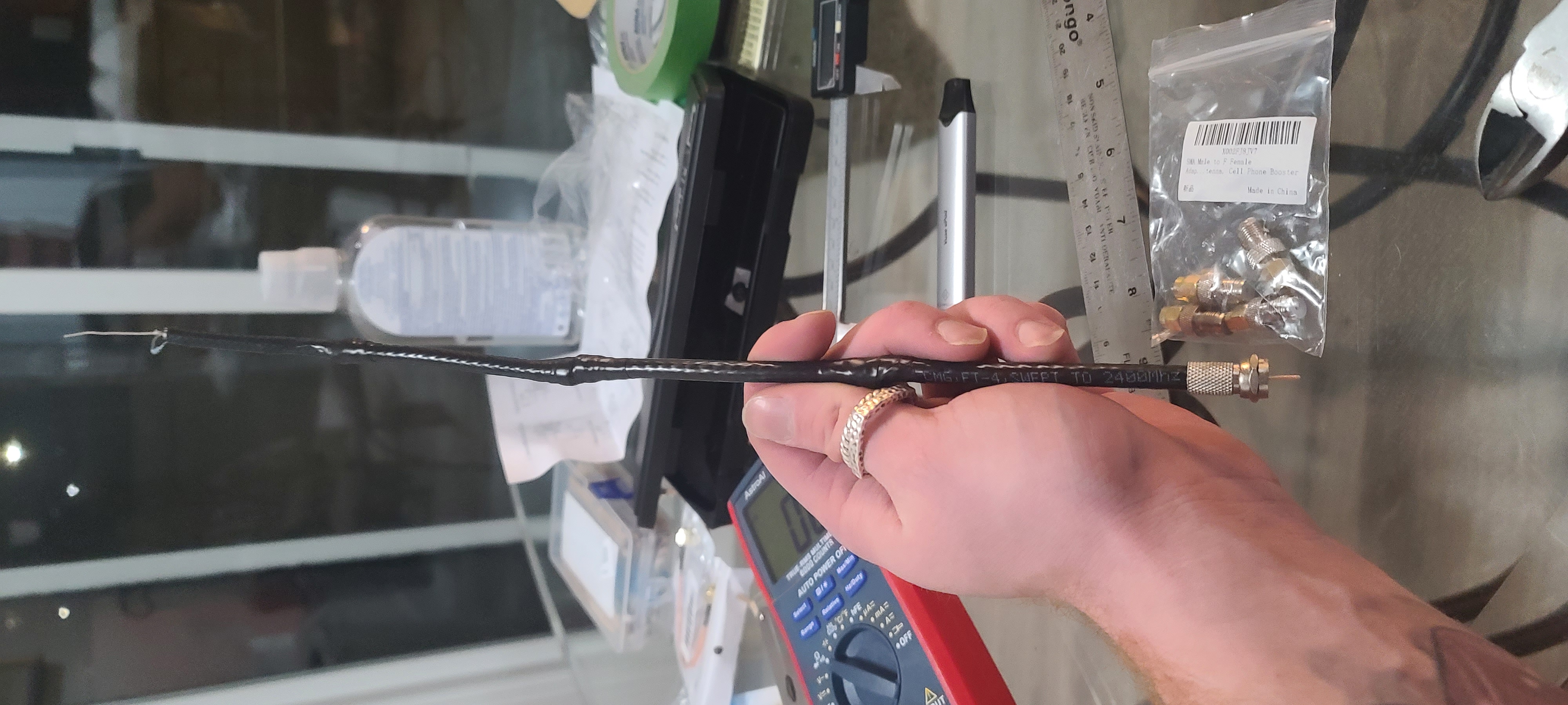
Figure 6: The 4 Section, 1/2 Wavelength COCO Antenna
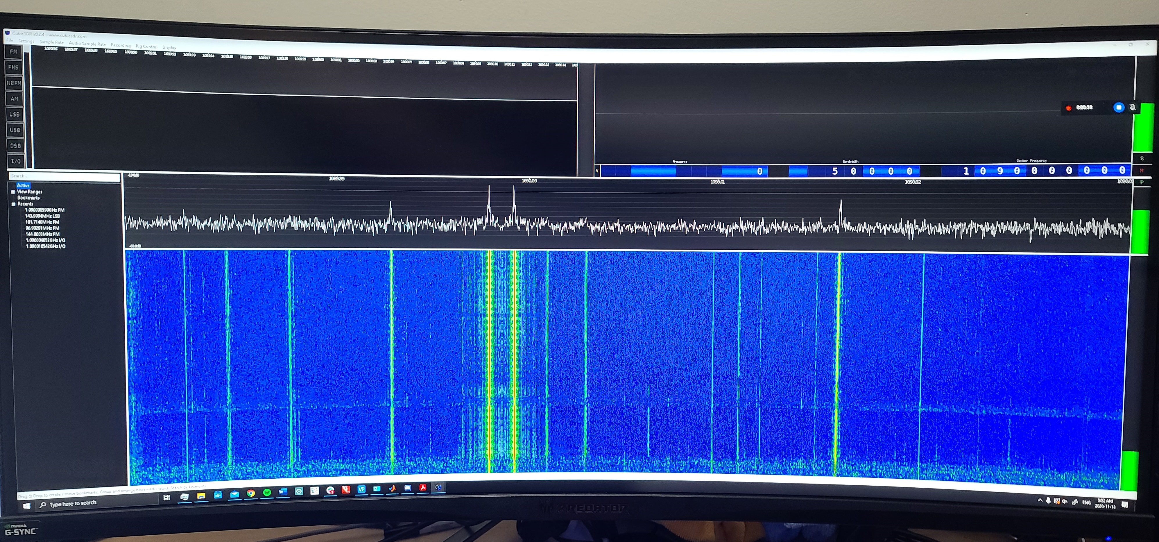
The two antennas were fully constructed and then testing using CubicSDR.
An image of both antennas side-by-side, as well as the testing results, are shown in figures 7 and 8 respectively.
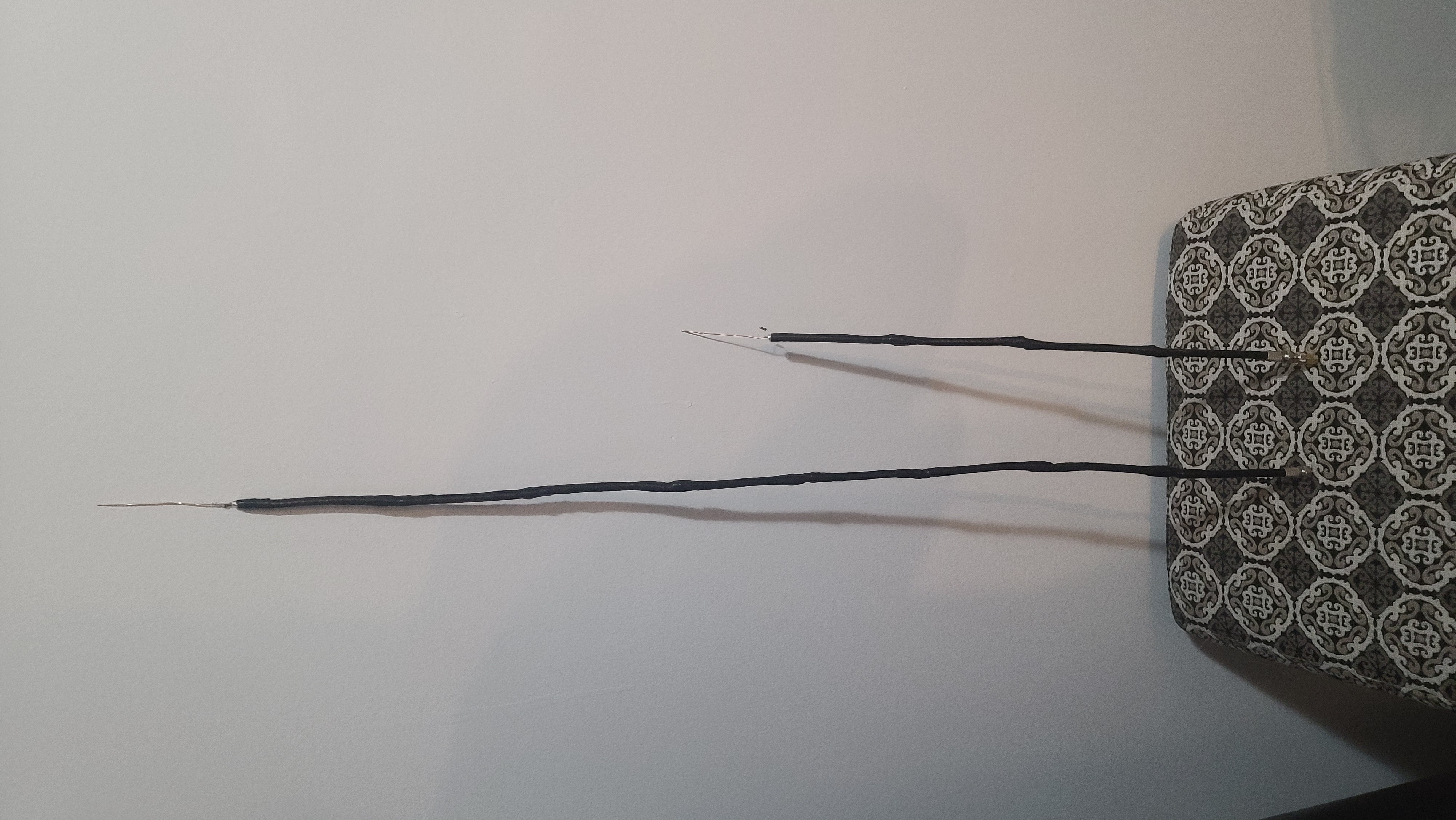
Figure 7: The 8- and 4- Section COCO's
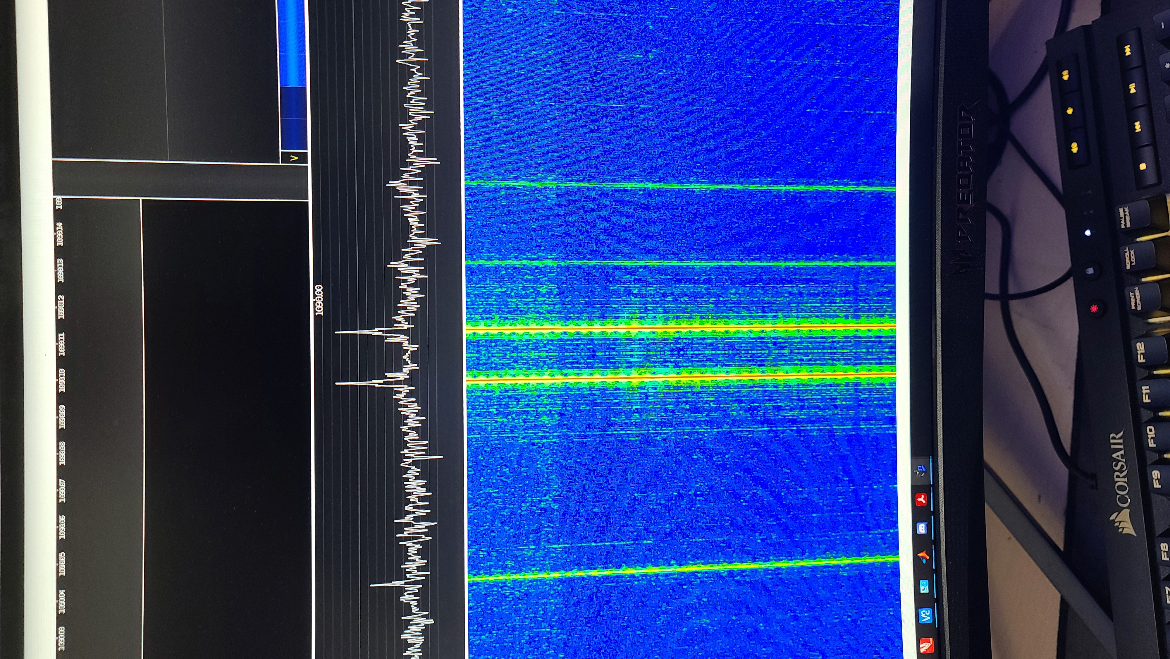
Figure 8: CubicSDR Testing
The 8-section coco antenna was confirmed to work better when tested in CubicSDR and thus, the antenna was taped to a window and a Raspberry Pi 4 with an LCD screen
was connected to the SDR dongle; the dongle used a series of adapters (SMA to Coax and vice-versa) to connect an ADSB filter made by FlightAware and a Nooelec wideband
Amplifier (see figure 9). While taped to the window, the antenna was able to catch a plane at a distance of 134.2 km, as shown in figure 10.
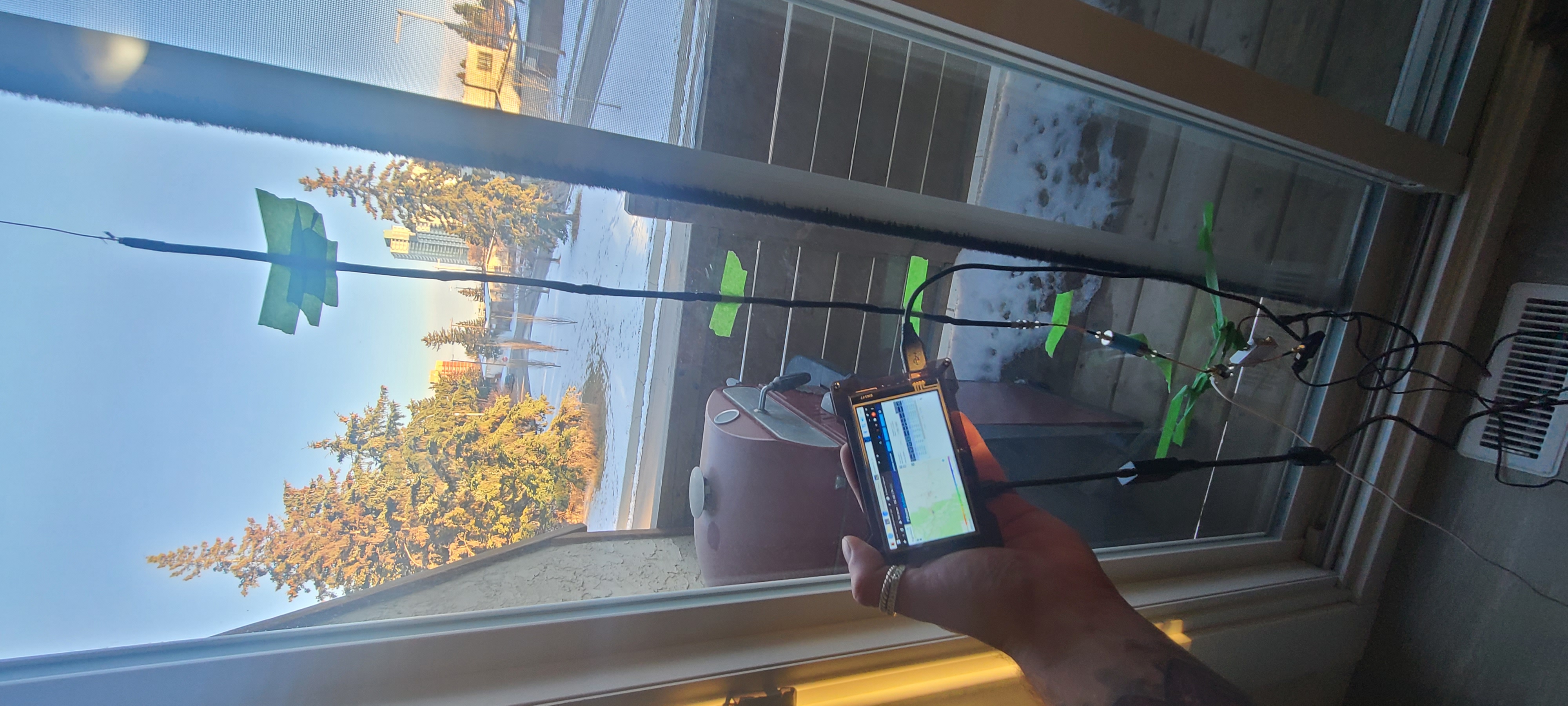
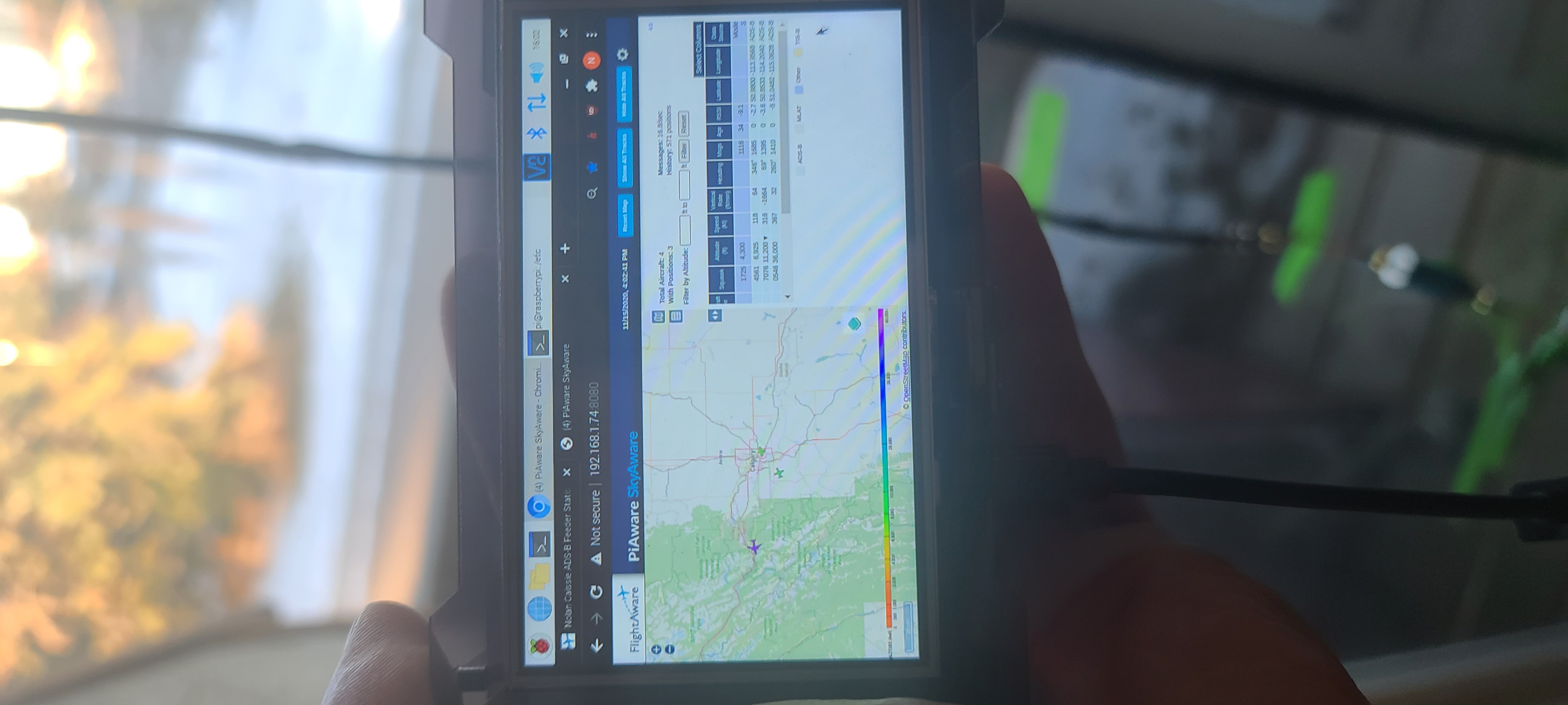
Figure 9: Testing the PiAware Software, Antenna, Filter, and Amplifier
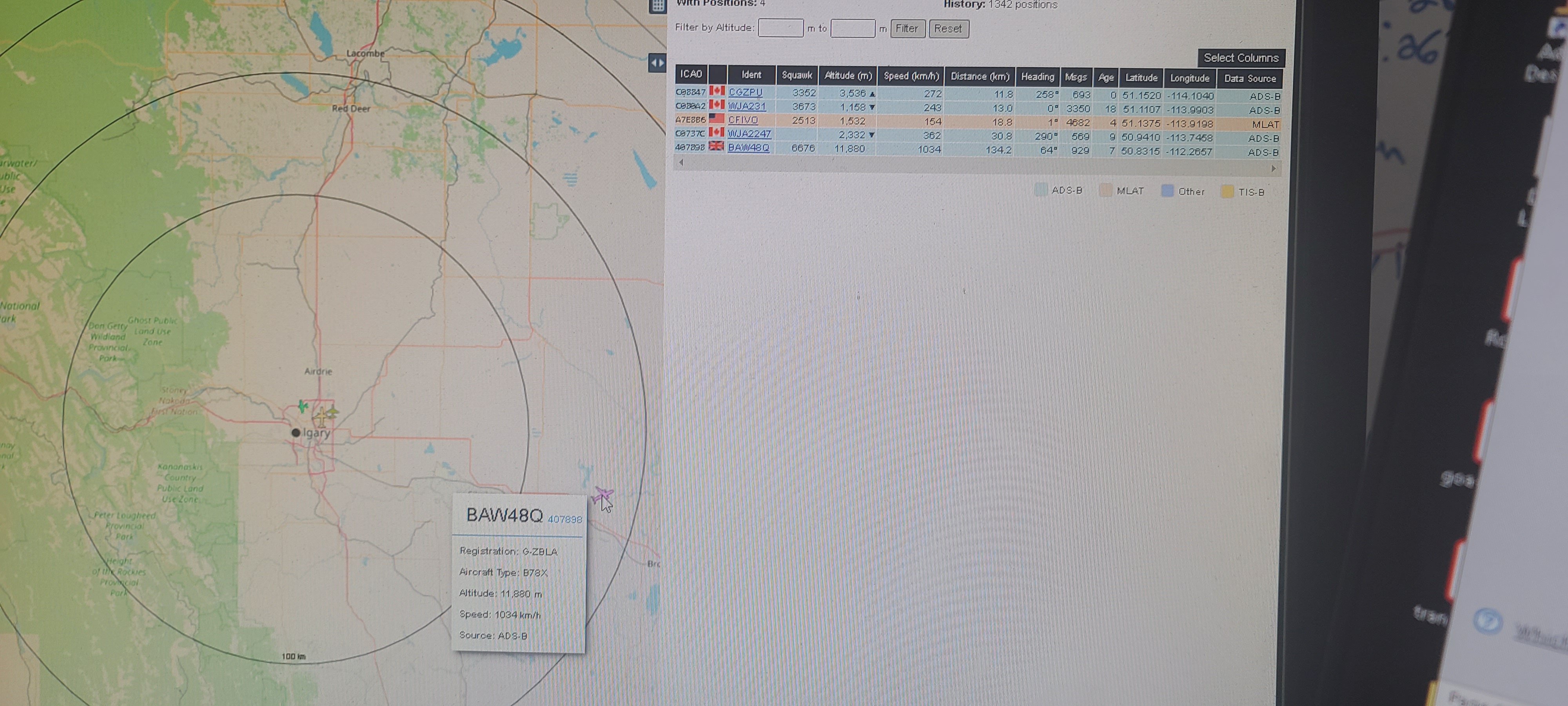
Figure 10: Airplane Tracked at 134.2 km
A junction box with a clear front cover, PVC electrical conduit, brackets, seals, an end cap for the conduit, PVC cement, and a mounting bracket were purchased with the intent of building a proper weatherproof
outdoor ADSB radar system. Unfortunately, the junction box ended up being too small to fit the Raspberry Pi with the LCD screen attached, and time was running out due to my engineering course load.
In the meantime, the system components were placed into a Tupperware container and sealed which was sealed for weatherproofing; the 8-section antenna was placed inside the PVC conduit and the end cap was placed on top;
a conduit bracket was placed on the outside of the PVC conduit and several pieces of duct-tape were stuck to each other (adhesive sides together) to create a strong piece of material; screws were then placed through the tape to
mount the system on the patio railing of my home. The resulting setup is shown in figure 11.
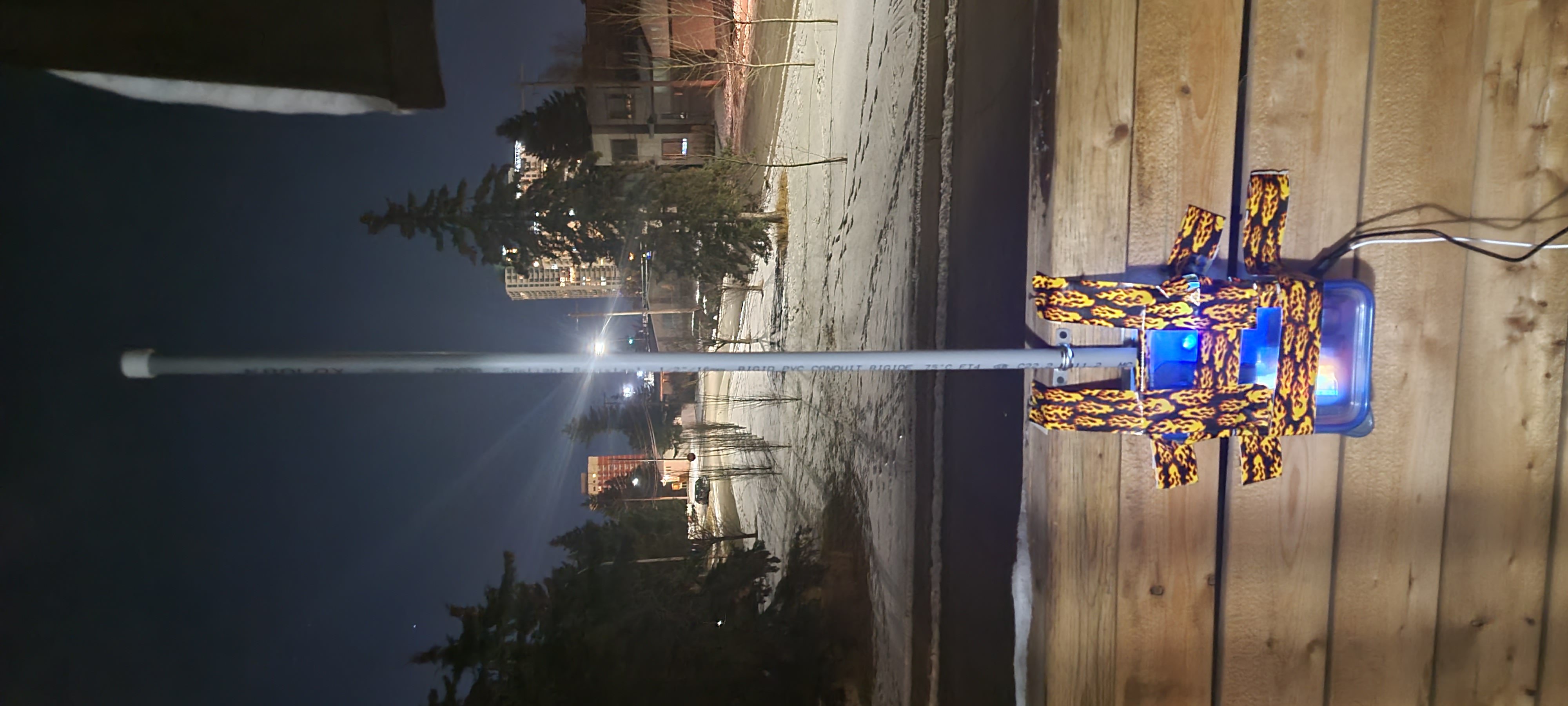
Figure 11: The Semi-Final Project Setup
Results
Once the setup was placed outside, the ADSB radar system began picking up many more airplanes. This is shown in Figure 12, where distances of 263.7, 246.3, and 225.5 kms were seen at the same time.
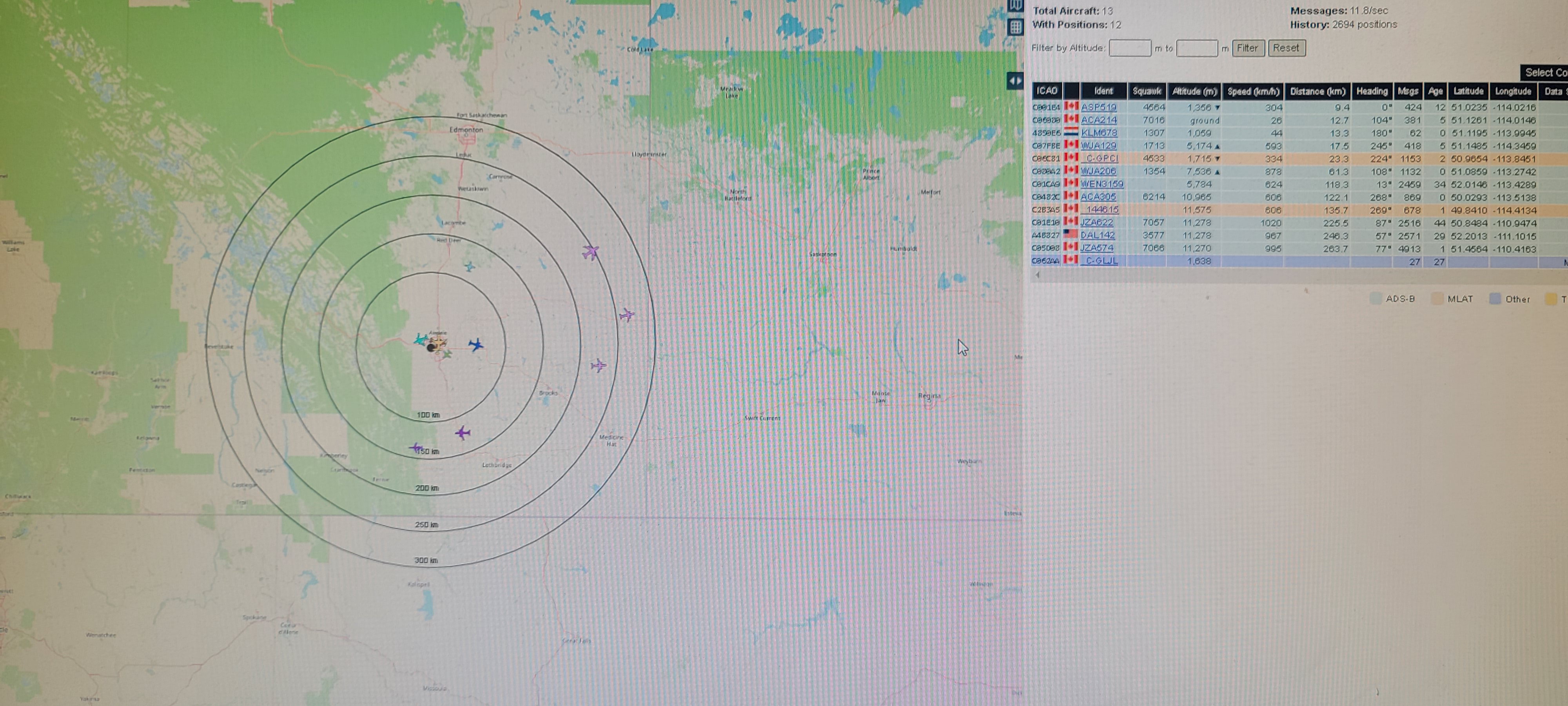
Figure 12: Airplanes Tracked at 263.7, 246.3, and 225.5 kms
Several airplanes were located farther away from this; in figure 13, an image of an airplane tracked at 272.5 km is shown.
-Figure-13.jpg)
Figure 13: Image of flight JZA574
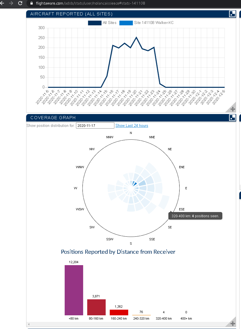
Some airplanes were detected over 320km away. Although I was unable to view them live, flightaware stored a record and coverage graph which can be shown in figure 14.